
When someone notices that two 8-bit DACs can be bought for less than one 16-bit DAC, a classic question is often asked: Why can’t you simply take two 8-bit DACs, assign one to the MSByte, the other to the LSByte, sum their outputs in a 28:1 ratio, and get 16 bit resolution (or near) for cheap? The likewise classic (but disappointing) answer is: Well, you can try, but you probably won’t like the result. This prediction is usually true mainly because of two factors: #1, poor differential nonlinearity (DNL), and #2, mismatch between typical 8-bit DACs.
The DNL of classic “resistor ladder” architecture DACs, typified in Figure 1, is seldom much better than the ~1/2 lsb that’s good enough to guarantee monotonicity, but only just.

Figure 1 The DNL typical of classic “resistor-ladder” DACs.
Consequently, when two such “classic” DACs are combined, very little improvement in useful resolution can happen. Fortunately, there’s an alternative. The inherent DNL of a “resistor string” type DAC is much better, as illustrated in Figure 2.

Figure 2 The DNL typical of “string” type DACs (e.g., TLV5624).
So, provided the right DAC architecture is chosen, is there hope after all for our money-saving plan?
Unfortunately, #2, the mismatch problem, remains unsolved. Two 8-bit DACs just can’t be expected to have output scale factors that match and sum to a result that’s significantly more accurate than required for 8-bit precision—clearly inadequate for our extended resolution application. However, what if both bytes of the 16-bit input could be converted by the same DAC? One DAC can reasonably be expected to accurately match itself!
A recent design idea (DI) suggests how this might be done (i.e., get one DAC to do double duty). In the earlier DI, the Shannon Decoder concept (see Figure 3), is explained. It employs (what is effectively) a 1-bit DAC to do multi-bit digital to analog conversion by the dynamic summation of successive conversions in a simple T/ln(2) RC time constant.

Figure 3 The Shannon decoder dynamic DAC.
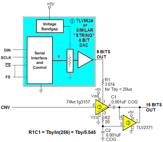
The trick that might be useful here is this: the Shannon Decoder principle isn’t limited to working with a 1-bit DAC. If instead of a time constant of RC = T/ln(21) the constant is made to be T/ln(28), then an 8-bit DAC could be accommodated. This is done in Figure 4.

Figure 4 The Shannon decoder principle applied to extending 8-bit DAC resolution.
U1 is an 8-bit, voltage output, resistor-string type DAC (e.g., TLV5624) controlled by a standard SPI serial interface, plus a separate output bit (CNV = Convert/-Hold).
Each conversion cycle is 2Tby = 40 µs long (for a 25kHz update rate) as illustrated in Figure 5.

Figure 5 The Shannon conversion sequence.
As the cycle begins with loading the Lsby of a 16-bit conversion value. Simultaneous assertion of Frame Sync (FS) and Convert (CNV) outputs the Lsby value and switches U2 so that R1 is connected to C1, creating a Shannon summation time constant of
R1C1 = Tby/ln(28) = 3.610 µs.
Consequently, after the 20 µs Tby interval, the charge on C1 is
Vc1 = (256/28)Lsby = Lsby.
While that’s happening, the Msby is loaded over the SPI interface so that when the second FS pulse occurs the Msby value is output, beginning its accumulation by the R1C1 time constant, while the previously accumulated Lsby de-accumulates.
After the second Tby = 20 µs interval,
Vc1 = (256/28)Msby + (256/216)Lsby = Msby + Lsby/28,
which is the final 16-bit result, and the conversion cycle is complete.
CNV now returns low, causing Vc1 to be sampled and transferred to C2 by unity-gain follower U3, where it is held until updated by subsequent conversion cycles.
Stephen Woodward’s relationship with EDN’s DI column goes back quite a ways. In all, a total of 64 submissions have been accepted since his first contribution was published in 1974.
Related Content


