
[ad_1]
Introduction To Orange Raspberry Pi Pico Intermediate Kit
We all know that the Raspberry Pi Pico board is a small size, high-performance microcontroller. And these days, we can see this board has gained an intense amount of popularity in the IoT sector due to its small size and high performance.
In this blog, we will discuss how to connect the various sensors and components to the Raspberry Pi Pico board. And to communicate with those sensors, we’ll be using the Python programming language and the Thorny IDE.
If you are new to the Python programming language, there is no need to be concerned because I have included all of the necessary information related to the python programming language in the booklet.
If you are new to the Python programming language, you can use the booklet as a guide.
So, that was an overview of the Raspberry Pi Pico kit. In the following section of this blog, we will understand the interfacing of the LED with the Raspberry Pi Pico.
Interfacing The LED And The Switch With The Raspberry Pi Pico
We learned how to blink the onboard LED in a previous blog. In this section, we’ll connect an external LED to the Raspberry Pi Pico and will control that LED with the help of the Switch.
Before we get into interfacing, let’s understand the basics of LEDs and switches.
As we all know, the Light Emitting Diode (LED) emits light when the appropriate voltage is applied across the LED’s anode and cathode terminals.
When we connect VCC to the anode terminal of the LED and GND to the cathode terminal of the LED, the LED flashes.
If we talk about the switches, they are electronics components that are used to connect two points. In our daily lives, we use switches.
There are different types of switches are available in the market. We can use these different switches for different purposes. We use
This was the basic introduction to the switch in the next part of the blog we will learn to interface the switch with the Raspberry Pi.
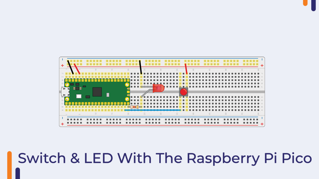
Interfacing Diagram For The Switch And The LED With The Raspberry PI Pico
We can move on to the interfacing section now that we’ve covered the fundamentals of components.
Please see the following image to understand how the switch is connected to the Raspberry Pi Pico.
Please wire the switch and LED together as shown in the image below. In the image below, you can see that we used a 320ohm resistor. This resistor is used to protect the led from overcurrent.
This is due to the fact that the LED we used here requires 20mAmp current, and if the current level exceeds this, the LED will burn out. That is why we used the resistor to keep the LED from being damaged.
Please Note: – You will damage the Raspberry Pi Pico board if you do not use resistors.
I hope you’ve completed the component interfacing with the Raspberry Pi Pico board.
We will now begin working on the programming portion. We can use the following python code
Okay, there’s something important I’d like to mention to you about coding. Please read the following section to know more about that part.
Coding Part
In this example, we want the LED to turn on when the button is pressed. But how will the pico board know that the LED is an output device and the switch is an input device?
The answer is that we are running micropython on the Raspberry Pi Pico board, and in order to tell the pico board which device is an input device and which is an output device, we must define the pin modes.
The following line of code was used in the following code to inform the Raspberry Pi Pico about the mode of the pin.
led = Pin(15, Pin.OUT)In the preceding example, we are creating an object of the Pin class and passing it two parameters. The pin number is the first parameter, and the method is the second.
When you type the above statement, the Raspberry Pi Pico board will recognise that the component connected to pin number 15 is the output device.
We can use the same method to define the other pins on the pico board as output pins.
If you want to define an input pin, simply change the second parameter to Pin.in. If you write the code in this manner, the Raspberry Pi Pico board will convert that pin to an input pin.
Example:
led = Pin(14, Pin.in)In the preceding example, the Raspberry Pi Pico will use the 15th number pin as an input pin.
This was the section on coding. You can now copy and paste the following code into the Raspberry Pi Pico board.
from machine import Pin
import time

led = Pin(15, Pin.OUT)
button = Pin(14, Pin.IN, Pin.PULL_DOWN)

while True:
    if button.value():
	    led.toggle()
        time.sleep(0.5)
In the above code we have used a few modules. If you want to know more about the above stuff then please download the booklet.
So, in this way we learned to control the LED using the Raspberry Pi Pico Board and the switch.
If you have any doubts then please let us know in the comment section.
In the next part, we will learn the interfacing of the RGB module with the Rasberry pi pico board.
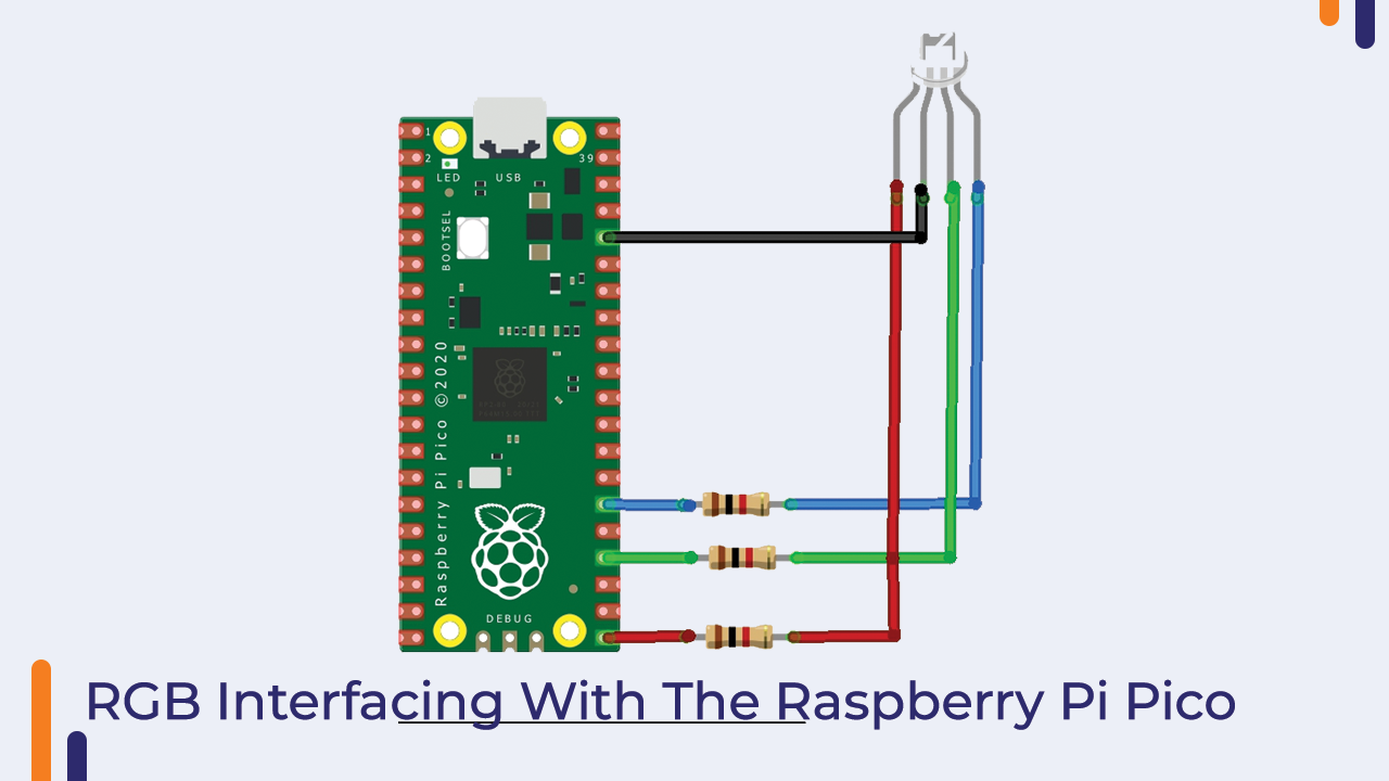
Interfacing of The RGB Module With The Raspberry Pi Pico
Unlike LEDs, RGB modules can also be used as output devices. The RGB module has four output pins. To turn on this RGB Module, connect these terminals to the Raspberry Pi Pico.
We have connected GPIO16, GPIO18, and GPIO20 to the led module’s B, G, R and the GND pin of the raspberry pi to the GND of the led module.
Please see the image below to understand the interfacing diagram.
Now, Connect the Pico board with the computer using micro USB cable.
Coding Part
OK, Now, in order to turn on the led, we must define the mode of the pin as an output. In the following code, we used the same method that we discussed earlier to define the mode of the pin.
You can now copy the code and upload it to the Raspberry Pi board.
from machine import Pin
import utime

red = Pin(16, Pin.OUT)
green = Pin(18, Pin.OUT)
blue = Pin(20, Pin.OUT)

while True:
    red.value(1)
    green.value(1)
    blue.value(1)
    utime.sleep(1)

    red.value(0)
    green.value(1)
    blue.value(1)
    utime.sleep(1)

    red.value(1)
    green.value(0)
    blue.value(1)
    utime.sleep(1)

    red.value(1)
    green.value(1)
    blue.value(0)
    utime.sleep(1)
When you will upload the above code to the board and if you did everything correctly then the RGB module will start emitting different colours. If this is not happening then you will have to crosscheck the connection.
So, in this way, you learned to interface the RGB Module with the Raspberry Pi Pico board. If you have any doubts then please let me know in the comment section.
In the next part of the blog, we will learn to interface the IR module with the Raspberry Pi Pico board.
Interfacing The IR Module And Buzzer With The Raspberry Pi Pico Board
IR Modules are used to implement a Proximity Sensor Application (Obstacle Detection) (Obstacle Detection). In this example, we will see how to connect the IR module to the Raspberry Pi Pico.
An IR Sensor Module is made up of three components: an IR Transmitter, an IR Detector, and a control circuit.
An IR LED is typically used as an IR Transmitter, and a Photo Diode or a Photo Transistor is typically used as an IR Detector. The control circuit is made up of a Comparator IC and other necessary components.
When it comes to the Buzzer module, it has three pins.
- GND – You can connect this pin to the GND pin of the Raspberry Pi Pico board.
- VCC – This pin to the 3.3v pin of the pico board.
- Signal – This pin to the GPIO pin of the pico board. In this example, we have connected this pin to the 18 pin of the Raspberry Pi Pico board.
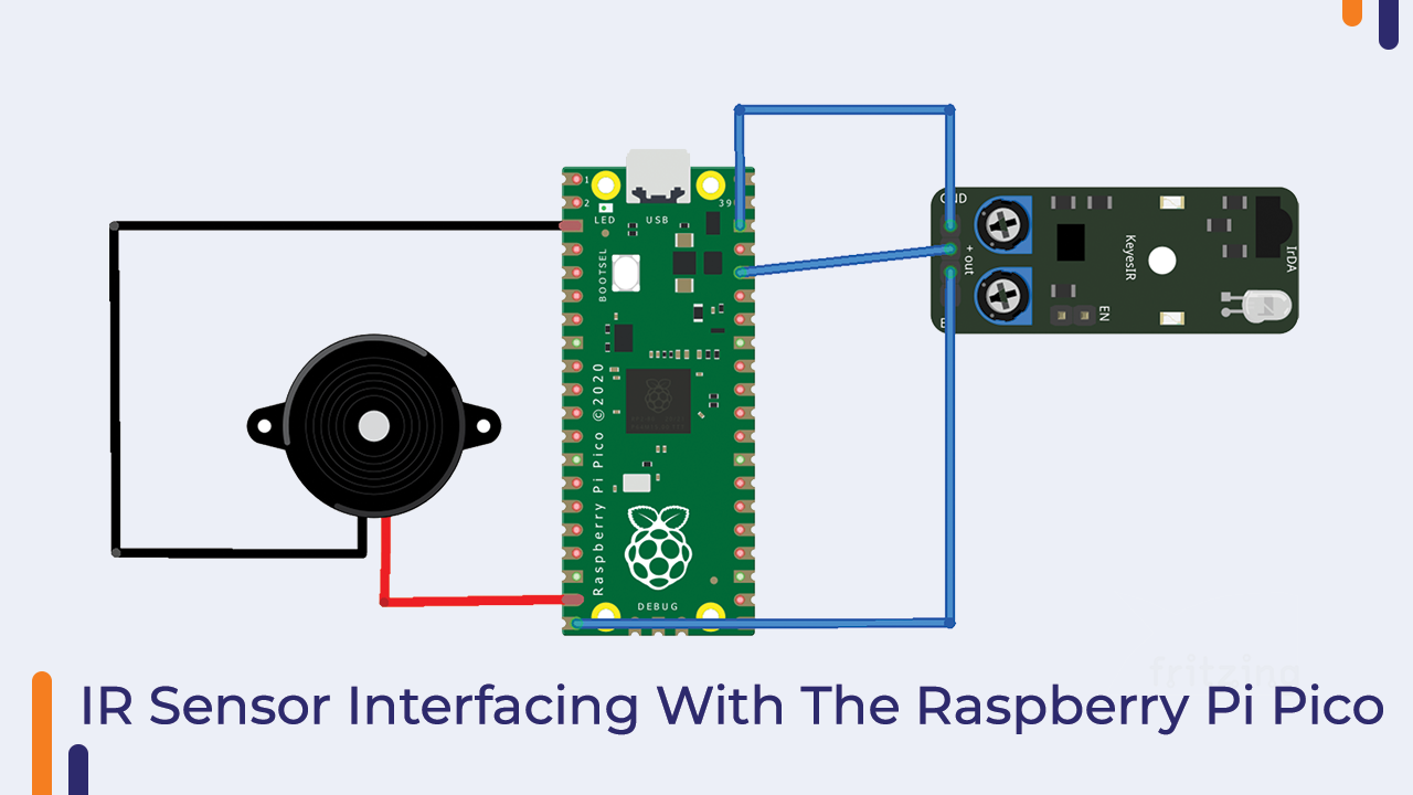
Raspberry Pi IR Sensor And Buzzer Interface
In this section, we’ll start interfacing the IR Sensor Module to the Raspberry Pi.
The IR module, as we know, has three output pins. Two of the three output pins are power pins, and one is a signal pin.
We will have to connect the signal pin of the IR Module to the GPIO pin of the raspberry Pi Pico board any those power pins of the module to the Power pins of the raspberry Pi.
The diagram below depicts how to connect the buzzer module and the IR Module to the Raspberry Pi.
Please see the image below for a better understanding of the interfacing diagram.
So, this was about the interfacing diagram, please take a look and if you have any doubts then please let us know. In the next part of the blog we will talk about the coding part.
Coding Part
The code for connecting an IR sensor to a Raspberry Pi is provided below.
We can use the above code to detect the object. When we place an object in front of the module, the infrared light from the IR LED is reflected back and lands on the Photo Diode.
The photodiode then begins to conduct. As a result, we will receive LOW-level signals on the Raspberry Pi Pico board’s GPIO pin.
After receiving the low-level signals, we have used the following line of the code to turn on the buzzer module.
from machine import Pin
import utime

buzzer = Pin(16, Pin.OUT)
button = Pin(15, Pin.IN, Pin.PULL_DOWN)

while True:
    print(sensor.value())
    if sensor.value() == 1:
          led.value(0)
    else
	  buzzer.toggle()
    time.sleep(0.5)
So this is how we learned how to connect the buzzer and IR modules to the Raspberry Pi Pico board.
Conclusion
In this way, we learned to interface electronic components with the Raspberry Pi Pico board and also learned to define the modes of the pins. If you have any doubt regarding any of the sections discussed in this blog, please let me know in the comment section.
We will be happy to assist you.
[ad_2]


