

[ad_1]
The ESP32-CAM is a development board with an ESP32-S processor, an OV2640 camera, several GPIOs for connecting peripherals, and a microSD card slot for storing images when communication is not possible.
The ESP32-CAM module is rapidly gaining popularity in applications that require image broadcasting, facial recognition, image processing, and, most importantly, built-in WiFi and Bluetooth.
Speaking of the orange ESP-32 Kit, in this kit, you will find everything you need to get started working on the ESP-32 development board.
How To Connect The FTDI Module TO ESP-32 Module?
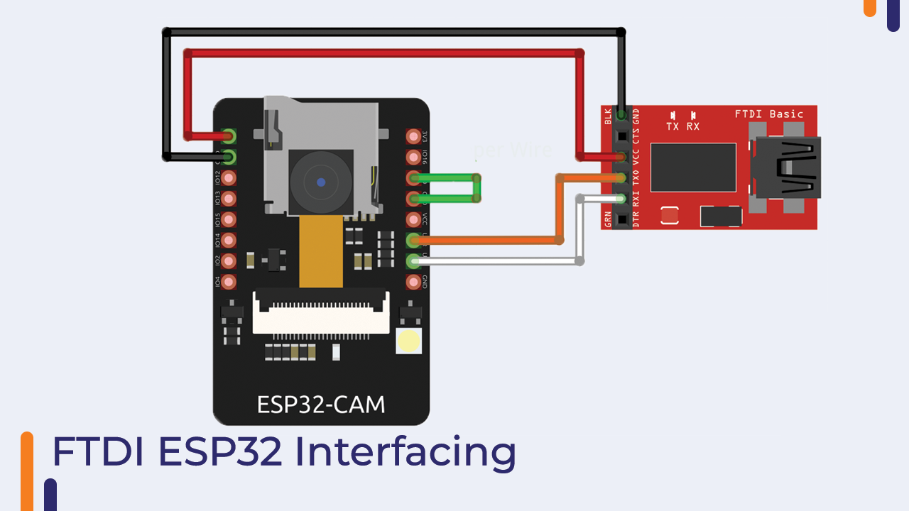
The Arduino IDE can be used to program our development board, but we’ll need an FTDI to do so. To connect the FTDI Module to the FTDI Module, follow the steps below.
It is important to note that the FTDI adapter must be set for a 3.3-volt VCC output rather than a 5-volt VCC output because we will be powering the ESP32-CAM with the 3.3-volt power pin.
You should also take note of connecting GPIO 0 pin to the Ground pin.This connection is only necessary while programming the ESP32-CAM.
When you’ve finished programming the module, power off the board and remove that jumper wire.
Now talking about the Rx and Tx pin, Connect the FTDI TX to the Board RX and the FTDI RX to the Board TX.
Please see the image below to get started with the interfacing.
We can now connect our Module to the computer and start working with the board but before that we will have to install the board on the Arduino IDE.
Installing The Board on The Arduino IDE
To program the ESP32-CAM board with the Arduino IDE, you must have both the Arduino IDE and the ESP32 board installed. If you have not yet installed the board, please proceed with the steps below.
Before you begin, ensure that you have the most recent version of the Arduino IDE installed on your computer. The most recent version is available at Arduino.cc.
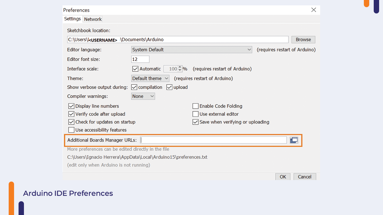
- In your Arduino IDE, go to File> Preferences
- Enter https://dl.espressif.com/dl/package_esp32_index.json into the “Additional Board Manager URLs” red field in the figure below. Then, click the “OK” button.
- Open the Boards Manager. Go to Tools > Board > Boards Manager
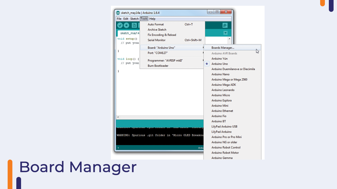
- Search for ESP32 and press install button for the “ESP32 by Espressif Systems“. It should be instaled after a few seconds.
- The ESP32-CAM board should be ready after you complete these steps.
Now Connect the ESP32 board to your computer. Open the Tools > Board menu in your Arduino IDE and select the board, as shown in the image below.
In our case, the AI-Thinker ESP32-CAM is used. Once you’ve selected the correct port, you’re ready to program.
Setting Up The Arduino IDE
To upload code to the board, go through the following steps:
1. Go to Tools > Board and select AI-Thinker ESP32-CAM.
The ESP32 add-on board must be installed. If you do not do so, this board will not appear in the Boards menu. If don’t see the board there then follow the steps that are mentioned in the previous section.
2. Go to Tools > Port and select the COM port to which the board is connected.
3. Copy and paste the below code in the editor section and click on the upload button.
4. When the uploading process will finish, you will see the Done Uploading message in the output section of the Arduino IDE.
5. Now Disconnect the board and remove the jumper wire as mentioned in the interfacing section.
So, in this way, we learned to work with the ESP32 cam board using the Arduino IDE. If you have any doubts then please let us know in the comment section.
In the next part of the blog, we will talk about the interfacing of the LED with the ESP32.
LED (Light Emitting Diode)
We’ve all heard of the light-emitting diode. When the required operating voltage is applied to these diodes, they emit light, as the name implies.
It has two terminals, one for the anode and one for the cathode. In order to turn on the LED, connect these terminals to the supply’s vcc and GND pins.
LED Interfacing With The ESP32 CAM
Now that you understand the fundamentals of the LED, we can proceed and begin interfacing the LED with the ESP32 Cam board.
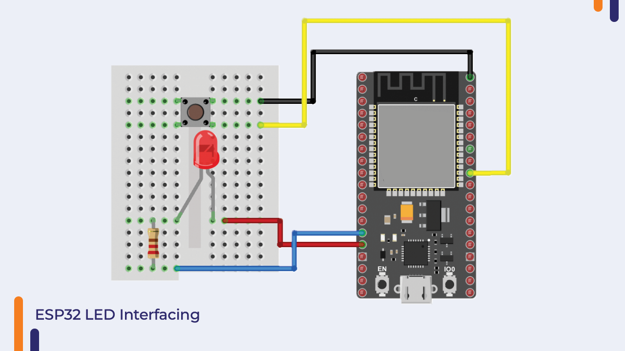
The LED in this kit has an operating voltage of 3.3v, and the ESP32 CAM board produces 5V on its GPIO pin. If we connect the LED directly to these pins, it will burn out.
So, in order to prevent the LED from being damaged, we must limit the voltage to the LED, which we can do by using a resistor.
We can connect the anode to the GPIO pin with a 320ohm resistor. Please see the image below for more information.
ESP 32- Cam Code For Controlling The LED
The following Code you can use to control the LED.
#define BUTTON_PIN 16 // ESP32 GIOP16 pin connected to button's pin
#define BUZZER_PIN 21 // ESP32 GIOP21 pin connected to Buzzer's pin

void setup() {
  Serial.begin(9600);                // initialize serial
  pinMode(BUTTON_PIN, INPUT_PULLUP); // set ESP32 pin to input pull-up mode
  pinMode(BUZZER_PIN, OUTPUT);       // set ESP32 pin to output mode
}

void loop() {
  int buttonState = digitalRead(BUTTON_PIN); // read new state

  if (buttonState == LOW) {
    Serial.println("The button is being pressed");
    digitalWrite(BUZZER_PIN, HIGH); // turn on
  }
  else
  if (buttonState == HIGH) {
    Serial.println("The button is unpressed");
    digitalWrite(BUZZER_PIN, LOW);  // turn off
  }
}
In this way, we learned how to work with the ESP32 Cam module. If you have any questions about this section, please leave them in the comments section.
In the following section, we’ll go over how to connect the switch to the ESP32 cam.
Switch Interfacing with The ESP-32 Cam
The switch is the component that is used to connect two separate pins. There are different types of switches are available in the market and each has its significance.
You can select the required switch based on the application.
The very common type of switch is the Rocker Switch. Despite the wide range of the switches, the reason behind selecting this switch is, this switch has a longer and life and the arching that will be caused due to the switching action of the switch is also minimized and hence these types of switches are preferred over the other types of the switch.
Ok So as you now know the basic things of the switch, we can now start working on the interfacing part of the switch.
Interfacing the Switch with the ESP-32 Cam
We’ve shared the Switch’s interfacing with the ESP-32 Cam board. In the image below, we have connected one end of the pin to the GND pin, the other end of the pin to the switch’s input terminal, and the out pin of the switch to the ESP32-CAM’s GPIO pin.
So that was the interfacing diagram. To complete the connections, please refer to the diagram below.

ESP32-CAM Code For Switch
#define BUTTON_PIN 16 // ESP32 GIOP16 pin connected to button's pin


void setup() {
  Serial.begin(9600);                // initialize serial
  pinMode(BUTTON_PIN, INPUT_PULLUP); // set ESP32 pin to input pull-up mode
  pinMode(BUZZER_PIN, OUTPUT);       // set ESP32 pin to output mode
}

void loop() {
  int buttonState = digitalRead(BUTTON_PIN); // read new state

  if (buttonState == LOW) {
    Serial.println("The button is being pressed");
    digitalWrite(BUZZER_PIN, HIGH); // turn on
  }
  else
  if (buttonState == HIGH) {
    Serial.println("The button is unpressed");
    digitalWrite(BUZZER_PIN, LOW);  // turn off
  }
}
So, the above code can be used to control the switch. In the preceding code, we used the input pull up function, but we could also have used the normal input reading function; however, we did not use the normal input reading function due to electromotive interference.
If we use the normal function to read the output, the output may be interference with by the surrounding noise and produce noisy signals. So, to prevent this from happening, we have used this input pull-up function here.
Ok So this was about the switch with the ESP-32 Cam board.
In the next part of the blog, we will talk about the interfacing of the Buzzer module with the ESP32-cam.
Buzzer
Buzzers are used in many instruments. It is used as an indicator in many systems such as home appliances, alarm systems, electronic bells.
Talking about the working principle of the buzzer, the buzzer converts electrical energy into sound energy.
When voltage is applied to the buzzer, the piezo crystal inside the plastic casing expands and contracts. This causes the plate to vibrate near the crystal and the sound you hear is of that vibration.
Changing the frequency to a buzzer changes the speed of the vibration and as a result, you hear a variety of sounds.
So, it was about the buzzer. There are two main types of buzzers. Active buzzer and passive buzzer. In the next section of this blog, we will understand the difference between these two types.
Difference Between Active And Passive Buzzer
As I mentioned earlier, there are many types of buzzers. Active buzzer and passive buzzer.
Talking about the active buzzer, it has an inbuilt oscillating source. Active buzzers start ringing as soon as they are turned on but in the case of passive buzzers, they do not have an inbuilt oscillating source.
If you want a passive buzzer to produce a sound signal, you must give a different frequency to the buzzer.
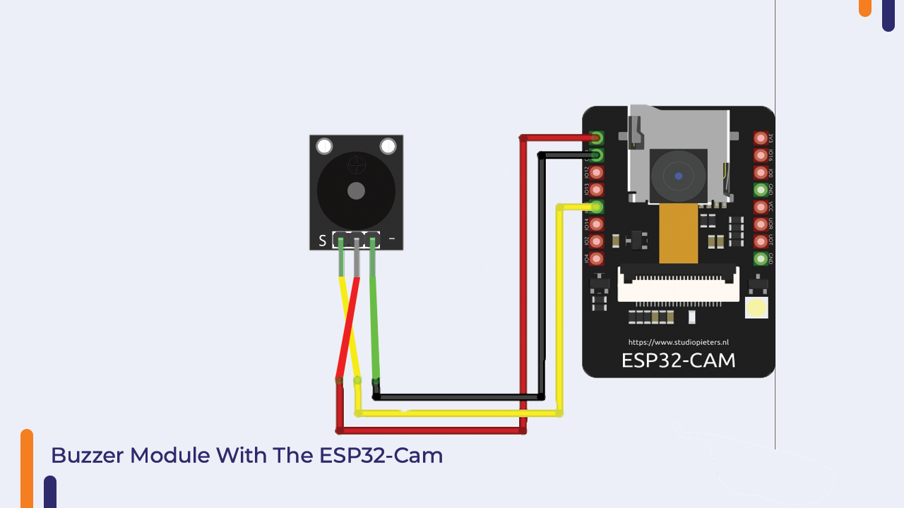
Interfacing Buzzer With The ESP32-CAM
No matter which buzzer you are using, it only has two pins. You can connect the vcc pin of the buzzer directly to the GPIO pin of the ESP-32CAM and the GND pin of the buzzer to the GND pin of the ESP-32CAM.
In my case, I have used an active buzzer. But you can use a passive buzzer, but remember, if you want to make a different sound from the passive buzzer, you have to give a varying frequency to the VCC pin of the buzzer.
Please check the interfacing diagram given below to understand the interfacing diagram.
As you have wired the buzzer. Now, we will move on to the ESP-32CAM code for the buzzer.
ESP32-CAM Code For The Buzzer Module
The code for the buzzer is very simple. All you need to do is use the digitalWrite function and apply a high or low voltage to turn the buzzer on or off.
You can use the following code to turn on the buzzer.
#define BUZZER_PIN 15 // ESP32 GIOP15 pin connected to Buzzer's pin

void setup() {
  pinMode(BUZZER_PIN, OUTPUT);       // set ESP32 pin to output mode
}

void loop() {

    digitalWrite(BUZZER_PIN, HIGH); // turn on
    delay(1000);
    digitalWrite(BUZZER_PIN, LOW);  // turn off
    delay(1000);
  }
}
In the next part of the video, we will talk about the interfacing of the PIR sensor with the Arduino.
PIR Sensor
You may have heard about the burglar system. Those burglar systems are designed to detect the motion. When a moving object comes in front of these systems, it detects the presence of the object and passes high-level signals to the controller.
But how does the PIR sensor detects the motion of the human or animal? PIR sensor is designed to measure infrared signals. It has two slots made of pyroelectric material. The more detailed information about the pyroelectric material has been shared in the booklet of this. You can refer to the booklet to know more about this material.
The voltage applied to this pyroelectric material changes as per the change in the temperature.
When the sensor is powered and there is no moving object then the sensor detects the three will not be changed in the output of the two slots of the PIR sensor.
when there will be a change in the temperature in the sensing area of the sensor then the output of the first slot of the PIR sensor changes and that change make the first slot to generate high electrical signals. Which results in a positive differential change in the output of those two slots.
when the object that caused the change in the sensing area, leaves the sensing area then the reverse happens. Whereby the sensor generates the negative differential change.
This change in the output then will be given to the controller where the controller executes the required operations based on the input received.
So this was about the working principle of the PIR sensor. In the next part of the blog we will talk about the interfacing of the PIR sensor with ESP32 Cam.
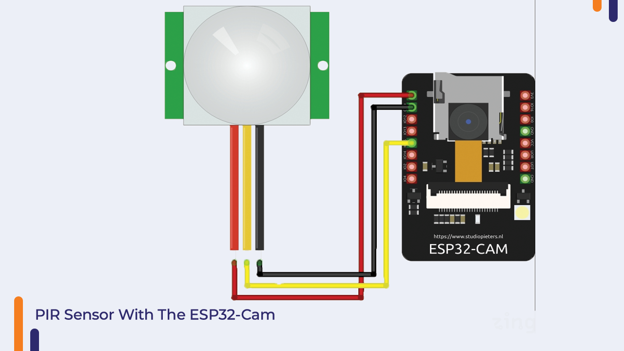
PIR Sensor interfacing With ESP-32 Cam
The output type of the PIR sensor is digital. It has three output pins. Two of them are the power pins and one is the output pin. The output pin should be connected to the digital pin of the ESP32 CAM and the power pins to the power port of the ESP32 cam.
There are two potentiometers are present on the sensor. Those two potentiometers are used to adjust the sensitivity and timing delay of the sensor. If the output of your PIR sensor is not correct then you can adjust these two potentiometers to get the correct output.
Please Note – The PIR sensor takes a few seconds to adjust the initial settings of the sensor. When you power on the PIR sensor it starts reading the surrounding temperature and once it collects all the required data, it starts producing the output.
So, if your sensor is not producing the correct output then please do not worry. It is adjusting the surrounding settings.
Please check the following image to understand the interfacing diagram.
ESP-32 Cam Code For PIR Sensor
You can use the following code to work with the PIR Sensor. We have not used any library in the code as the output type of the PIR sensor is digital.
Ok, so copy the code and start working with it.
#define timeSeconds 10


const int motionSensor = 15;

// Timer: Auxiliary variables
unsigned long now = millis();
unsigned long lastTrigger = 0;
boolean startTimer = false;


void IRAM_ATTR detectsMovement() {
  Serial.println("MOTION DETECTED!!!");

  startTimer = true;
  lastTrigger = millis();
}

void setup() {
  // Serial port for debugging purposes
  Serial.begin(115200);

  // PIR Motion Sensor mode INPUT_PULLUP
  pinMode(motionSensor, INPUT_PULLUP);
  // Set motionSensor pin as interrupt, assign interrupt function and set RISING mode
  attachInterrupt(digitalPinToInterrupt(motionSensor), detectsMovement, RISING);


}

void loop() {
  // Current time
  now = millis();

  if(startTimer && (now - lastTrigger > (timeSeconds*1000))) {
    Serial.println("Motion stopped...");

    startTimer = false;
  }
}
Conclusion:
So, in this way, we learned about all of the components included in this orange ESP-32 Cam IoT starter kit.
I hope you learned something new from this blog; if you have any questions or concerns, please let us know in the comments section.
We will be happy to assist you.
[ad_2]


