
Every PWM DAC needs analog filtering to separate the desired DC component from unwanted AC ripple. The simplest filter is the single-stage RC low-pass filter. It gives a Vrpp (ripple peak-to-peak amplitude expressed as a fraction of full-scale) of ~Tpwm / 4RC, where Tpwm = PWM cycle time, for the worst case of a 50% duty cycle. Clearly any desired degree of ripple attenuation can be achieved by making RC long enough (e.g., RC = 64Tpwm for Vrpp = 1/28 = one 8-bit lsb), but DAC response time will correspondingly suffer:
e.g., Response time = ~64ln(28)Tpwm = 355Tpm for 8 bits.
A two-stage cascaded RC filter (Figure 1) can do better (see Figure 2’s 41Tpwm settling), because the desired ripple attenuation can be achieved with much shorter RC time constants, e.g., Figure 1’s 702 µs contrasted with the 16 ms a single-stage RC would need.

Figure 1 A two-stage passive RC filter, the values are shown for 8 bits and 256 µs Tpwm.

Figure 2 A two-stage RC 8 bit, 1 lsb, 0.004 peak-to-peak ripple, and 41Tpwm settling time.
But what if 41Tpwm still isn’t fast enough? What can we do?
Of course the RC constants could be reduced as shown in Figure 3 with its 500 µs RCs, yielding a 30Tpwm settling. But now ripple swells to 1/128 = 2 lsb, which may be unacceptable.


Figure 3 The reduced RCs cause faster 30Tpwm settling but twice the ripple.
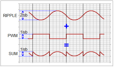
A solution is suggested with a closer inspection of the ripple waveform and its phase relationship to the original PWM, shown in Figure 4.


Figure 4 The semi-sinusoidal ripple is ~180o out of phase with PWM signal.
Each RC stage of the passive filter, in addition to attenuating ripple, also phase shifts it by approximately -90o. This results in the final ripple signal being delayed by a half-cycle and therefore inverted relative to the original PWM, which makes a simple passive summation equivalent to subtraction. The appropriate circuit is shown in Figure 5.


Figure 5 Circuit for the cancellation of ripple by analog subtraction without inverter.
The R3 R4 voltage divider sums a 1 lsb amplitude PWM component to reduce the net output ripple component by ~50% from 2 lsb to 1 lsb, the same attenuation achieved by Figure 1. The resulting output signal—with the same 30Tpwm settling time as Figure 4—is shown in Figure 6.


Figure 6 The net ripple and settling after passive PWM subtraction.
Although the topic of this writeup is ripple reduction without an active inverter, it’s still tempting to compare these results with an alternative (shown in Figure 7 and Figure 8). Its ~25Tpm settling is encroaching on twice the speed of Figure 1’s original dual RC’s 41Tpm without compromising 1 lsb Vrpp.


Figure 7 Circuit for a ripple filter with an active inverter.


Figure 8 The ripple cancelation with active inverter.
Stephen Woodward’s relationship with EDN’s DI column goes back quite a ways. In all, a total of 64 submissions have been accepted since his first contribution was published in 1974.
Related Content


