[ad_1]
This 5-color LED flasher circuit can be built using the popular 555 timer and 4017 decade counter ICs. It does not require any expensive components like a microcontroller.
The timer IC is used as an astable multivibrator to generate a clock pulse, which is fed to the clock input of the 4017. Outputs of the 4017 are connected to bases of five transistors to drive 20 LEDs of different colors, each with its current-limiting resistor.
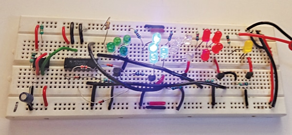
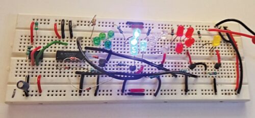
The 4017 advances to the next output every time it receives a clock pulse, causing the LEDs to turn on and off in sequence. The speed of the flashing can be adjusted by changing the values of the resistors and capacitors in the 555 timer circuit. The author’s prototype is shown in Fig. 1.

Required Components
| Parts List | |
| Semiconductors: | |
| IC1 | -555 IC timer |
| IC2 | -4017 decade counter |
| D1-D5 | -1N4148 signal diode |
| LED1-LED4 | -5mm red LED |
| LED5-LED8 | -5mm green LED |
| LED9-LED12 | -5mm blue LED |
| LED13-LED16 | -5mm white LED |
| LED17-LED20 | -5mm yellow LED |
| T1-T5 | -BC548 NPN transistor |
| Resistors (all 1/4-watt, ±5% carbon): | |
| R1 | -10-kilo-ohm |
| R2-R12 | -1-kilo-ohm |
| Capacitors: | |
| C1 | -100nF ceramic disk |
| C2 | -10µF, 25V electrolytic |
| Miscellaneous: | |
| CON1 | -2 pin connector |
| -9V or 12V battery | |
| -Breadboard | |
| -Jumper wires | |
LED Flasher Circuit Diagram
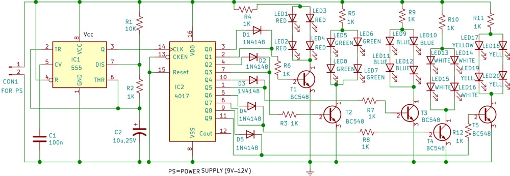
The circuit diagram of the 5-color flasher is shown in Fig. 2. The circuit comprises a 12V battery (or 12V adaptor), timer IC 555 (IC1), decade counter IC 4017 (IC2), five BC548 transistors (T1 through T5), five sets of 5mm red, green, blue, white, and yellow LEDs each, and a few other components.

If you have built 555 timer-related projects, you would be familiar with the IC. The timer IC’s pin 4 (reset) and pin 8 (Vcc) are connected to the voltage supply, which can be anywhere between 9V and 12V.
In this circuit, a 10k resistor (R1) is connected between Vcc and discharge pin 7 of IC1. A 1k resistor (R2) is connected between pin 7 and the junction of pin 2 (trigger) and pin 6 (threshold).
A 10µF capacitor is connected between pin 6 and the ground pin of the 555 timer, whose ground pin 1 (GND) is connected to the circuit’s ground. A 100nF capacitor is connected between pin 5 (CV) of the timer and the ground. The IC’s out pin 3 is connected to clock pin 14 of IC4017 (IC2).
Pin 16 of the decade counter IC2 is connected to the supply. Its pins 8 (VSS), 13 (CKEN), and pin 15 (Reset) are connected to the ground. The other pins of IC 4017 are outputs used to drive the LEDs for flashing.
Working
As mentioned earlier, the 555 timer IC works in astable multivibrator mode. Based on the above-mentioned components, the frequency of the output pulse is around 12Hz.
The output of the 555 timer is supplied as a clock input to the 4017 decade counter. This 12Hz frequency can be changed by changing the timing components R1, R2, and C2. In place of R2, you can use a pot to vary the output frequency.
Whenever there is a low to high transition on the clock signal, that is, on the rising edge, the output of the counter is incremented by 1. You cannot change the flash rate in this project as the astable multivibrator built around IC1 generates a fixed frequency.
IC2’s five outputs Q0, Q2, Q4, Q6, and Q8 are connected to the anodes of respective 1N4148 diodes D1 through D5. The remaining five outputs Q1, Q3, Q5, Q7, and Q9 are connected to the cathodes of respective 1N4148 diodes.
So, two consecutive outputs drive individual transistors T1 through T5. The bases of all these five transistors are connected to the outputs of 4017 to drive various color LEDs.
Here, we have used all ten outputs of 4017 to flash the LEDs. Outputs Q0 and Q1 control the red LEDs, outputs Q2 and Q3 control the green LEDs, outputs Q4 and Q5 control the blue LEDs, outputs Q6 and Q7 control the white LEDs, and outputs Q8 and Q9 control the yellow LEDs.
The four red LEDs are driven by transistor T1 when outputs Q0 and Q1 of IC2 go high. Likewise, the four green LEDs are driven by transistor T2 when outputs Q2 and Q3 of IC2 go high. This goes on for the blue, white, and yellow LEDs driven by transistors T3, T4, and T5, respectively.
The working of the circuit is simple. As soon as the power is switched on, the 5-color flasher starts flashing. First of all the four red LEDs glow, then the four green LED glow, followed by the four blue, white, and yellow LEDs. Thereafter the cycle repeats endlessly.
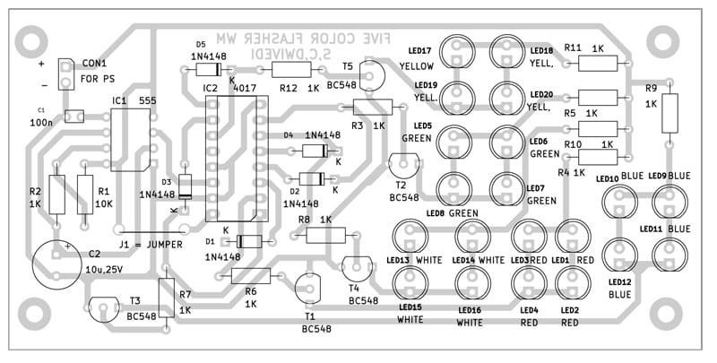
An actual-size, single-side PCB layout for the 5-color flasher is shown in Fig. 3 and its component layout is in Fig. 4. After assembling the circuit on PCB, enclose it in a suitable box. Fix all the 20 LEDs in a pattern of your liking, like a star or a circle.


CON1 is used to connect the 12V battery to the flasher circuit in a suitable box. If you are using a compact 9V battery, it can be accommodated within the box.
Download PCB and Component Layout PDFs: click here
S.C. Dwivedi is an electronics enthusiast and circuit designer at EFY
[ad_2]


